This paper presents a comprehensive system-level design for the electrical power and electric propulsion subsystems in microsatellites. The study begins with an overview of the subsystems typically integrated into microsatellite platforms, before focusing in greater detail on electrical power distribution and electric propulsion. Particular attention is given to the Hall Effect Thruster (HET), including its operating principle, advantages, and inherent limitations. A three-year mission scenario is considered to estimate annual velocity changes and corresponding power requirements, providing a realistic operational framework. The analysis incorporates orbital mechanics by examining the relationship between the Sun and satellite in terms of Earth’s radius, gravitational constant, mass, and eclipse duration. Satellite velocity is calculated across different orbital geometries, with additional consideration of drag forces that may arise in low Earth orbit. Building on this foundation, the paper concentrates on the design of a miniaturized HET tailored for a 75 kg satellite operating in a 1000 km circular orbit. Key design parameters such as thrust requirements, power demands, propellant selection, and component sizing are systematically evaluated. The proposed system enables small-scale orbital maneuvers through continuous monitoring of orbital velocity and feedback-based corrections. Furthermore, the paper details strategies for power distribution among subsystems and identifies the fundamental components required for implementation. By integrating propulsion and power considerations at the system level, the study demonstrates a viable pathway for enhancing the autonomy and maneuverability of microsatellites in extended missions.
| Published in | International Journal of Astrophysics and Space Science (Volume 13, Issue 4) |
| DOI | 10.11648/j.ijass.20251304.11 |
| Page(s) | 113-126 |
| Creative Commons |
This is an Open Access article, distributed under the terms of the Creative Commons Attribution 4.0 International License (http://creativecommons.org/licenses/by/4.0/), which permits unrestricted use, distribution and reproduction in any medium or format, provided the original work is properly cited. |
| Copyright |
Copyright © The Author(s), 2025. Published by Science Publishing Group |
Microsatellite, Hall Effect Trust, Velocity Maneuvers, Eclipse Cycles, Xenon
Parameter | Typical Range |
|---|---|
Average power generation | 70–120 W |
Peak power (sun-pointing) | 100–150 W |
Battery capacity | 40–120 Wh |
Main bus voltage | 12 V or 28 V |
Regulated lines | 5 V, 3.3 V, payload-specific |
Solar cell efficiency | 28–32% |
Power margin | 20–30% recommended |
Orbit Insertion ΔV | Station-Keeping / Orbit Maintenance ΔV | Attitude Control / Momentum Dumping ΔV | De-Orbiting ΔV | |
|---|---|---|---|---|
1 year | 10 - 50 m/s | 1 - 5 m/s per year | 1 - 5 m/s per year | - |
3 years | - | (3-15) m/s | (3-15) m/s | 150 – 200 m/s. |
 Mass flow rate (mass per unit time, e.g., kg/s).
 Parameter | Value (Typical) |
|---|---|
Orbit | LEO (sunlit fraction ≈ 0.64) |
Triple-junction GaAs efficiency | 28–30% |
Solar constant | 1,358 W/m2 |
Packing factor | 0.9 |
Degradation | ~2.5%/year |
Mission duration | 3 years |
Panel efficiency decay | ≈ 8% total |
Power budget margin | 20–30% |
Remote Power Controller (RPC) | Solid-State Power Distribution Switch (MOSFET switch) | Battery Charge / Discharge Regulator | Main Bus Switching Unit (MBSU) |
|---|---|---|---|
These are solid-state or electronic switches used in the PDU to turn on/off power lines. In NASA’s modular power architecture, the PDU uses RPCs as the switching element + fault isolation. | Many satellites use high-side MOSFETs (or back-to-back MOSFETs) as their “switches” to connect/disconnect power. These switches can be designed with current-limiting, soft turn-on, and telemetry of load current. | These are power converters/regulators that manage how the solar array charges the battery (Battery Charge Regulator, BCR) and how the battery discharges to the bus (Battery Discharge Regulator, BDR) or PDU. These circuits also often include switching elements to isolate battery or solar power sources when needed. | On more complex spacecraft, the solar + battery bus is managed by a switching unit (e.g., MBSU) that controls which power source is connected to the main bus. These units can cross-tie different power strings or switch between power sources. |
AST µFCU (Miniaturized Flow Control Unit) | CU Aerospace CAM Flow System | MEMS-Based Flow Control Module (ESA / Nano space) | SETS Xenon Feed System (XFS) |
|---|---|---|---|
AST offers a µFCU specifically designed for xenon. According to their data, the µFCU design can support a flow range from 0.01 sccm to 100 sccm. 0.01 sccm of xenon is quite low; depending on pressure you might be able to set up the system so that 0.015 mg/s is in its controllable region. Very lightweight: the EM model weighs ~62 g. Uses PWM (pulse-width modulation) solenoid for flow control. Has built-in filters (e.g., 5 µm) to protect against particulates. Limitation: their documented maximum “full scale” for some µFCUs is up to 100 sccm, but you might need to request a customized low-flow version tuned for your small flow. | CAM Flow is designed for very stable low flows and has been tested on a 600 W Hall thruster. Input pressure: up to 2,500 psi (~~172 bar) supported, so high-pressure xenon tanks are possible. Flow control accuracy: ±3% demonstrated. Their architecture uses a “fixed frequency Boolean valve” (i.e., pulsing valves), which is very useful for long life and very fine mass control. This is likely a very good candidate, since your flow (~0.015 mg/s) is well within very low-flow regimes that CAM Flow might handle; but you will need to check with CU-Aerospace for the lower bound and any required calibration for that flow. | Under ESA’s MEMS FCM project, they developed a MEMS flow control module that includes a micro proportional valve + flow sensor + pressure + temperature sensors. The flow control range of their MEMS FCM is 1 to 18 mg/s for xenon, with high resolution. They report the ability to control very small flow changes — “changes around 50 µg/s” (which is 0.05 mg/s) demonstrated. Pros: very compact, integrated sensing + control, low power. Cons: might not go as low as 0.015 mg/s in standard versions; depends on the exact MEMS model. Also, EM-level, not necessarily fully flight-qualified for all uses (depending on your risk tolerance). | SETS offers a xenon feed system with flow control. Their XFS nominal flow rate: up to 3 mg/s for anode, 0.5 mg/s for cathode according to their spec sheet. This is much higher than your 0.015 mg/s, so this might not be ideal unless you operate it in a very throttled regime or with a restrictor/orifice downstream. Advantages: mature system, likely robust for higher flow missions, but not optimal for ultra-low flow. |
Radiation-Tolerant Microcontrollers (most common) | Radiation-Tolerant Processors (high-end microsats) | COTS SBCs (Commercial ARM boards) – with protection | FPGA-Based Soft CPUs | Dual-CPU Architecture |
|---|---|---|---|---|
Used in low-to-medium complexity missions. | Suitable for spacecraft with heavy ADCS or payload demands. | Used in cost-sensitive missions (LEO, <3 years lifetime). | Allows custom CPU logic with radiation mitigation. | Common in mi crosatellites: |
Examples: ARM Cortex-M7 / M4 / M33 (rad-tolerant versions) Microchip SAMRH71 (rad-hard ARM Cortex-M7) LEON3FT (fault-tolerant SPARC) Gaisler NOEL-V (RISC-V, rad-tolerant versions emerging) | Examples: LEON4 / LEON3FT (Cobham/Gaisler) RAD750 (classic but high power) NanoXplore NG-Large / NG-Ultra FPGA CPU | Examples: ARM Cortex-A series Raspberry Pi Compute Module (with shielding & watchdogs) BeagleBone Black space-hardened versions | Examples: Microblaze (soft-core) LEON3 soft-core RISC-V custom soft-core Used when payload requires flexible digital processing. | Examples: High-performance CPU (e.g., ARM A53) → main mission operations Low-power safe-mode MCU (Cortex-M or LEON3FT) → recovery, FDIR |
Pros: Low power Safe for LEO microsatellites Easy software development | Pros: Very high reliability Used in many ESA/NASA missions | Pros: Very high CPU performance Low cost High memory Runs Linux easily | ||
Cons: Limited CPU power compared to SBCs | Cons: Expensive Higher power consumption | Cons: Low radiation tolerance (needs shielding + ECC + watchdog redundancy) | ||
Typical computing power: 100–2000 DMIPS |
Configuration A (Low-power microsat, ADCS + simple payload) | Configuration B (Medium-performance imaging satellite) | Configuration C (High-performance payload processing) |
|---|---|---|
ARM Cortex-M7 rad-tolerant MCU 300–600 MHz 512 KB–2 MB RAM Redundant MCU + watchdog Bootloader in rad-hard memory | LEON3FT or LEON4 ECC SDRAM 256–1024 MB RTEMS or Linux OS Hardware redundancy (cold spare) | ARM Cortex-A53/A72 with radiation mitigation Runs Linux Accompanied by safe-mode microcontroller SDRAM with ECC Thick aluminum shielding |
Power Switching Units (PSUs) | Voltage Regulation | Protection | Sensors | Communication Interface |
|---|---|---|---|---|
Turn each subsystem on/off. | High-efficiency DC-DC converters: Synchronous buck converters Radiation-tolerant converters Efficiency 85–94% | Resettable electronic fuses Latch-up protection circuits Current limiting Reverse voltage protection Soft-start for sensitive loads | Each power line has: Voltage sense Current sense Temperature telemetry All sent to the OBC. | PDB normally communicates using: CAN bus (standard) I2C (for CubeSat-type subsystems) RS-485 or UART (less common) |
Product | Description / Key Features |
|---|---|
GAUSS PCDU | From GAUSS S.r.l: a Power Conditioning & Distribution Unit with 4 regulated independent channels + 1 unregulated channel. PC/104 form factor. (Gaussteam) — Very configurable; each channel has switch, current limiter, telemetry (I2C); up to 6 A on some outputs. (Gaussteam) — Flight heritage: used on UNISAT-7. (Gaussteam) |
AAC Clyde Space – SmallSat PCDU (“STARBUCK Mini”) | A very reliable, flight-proven PCDU. (AAC Clyde Space) They also have the STARBUCK-NANO EPS which includes power distribution modules with latching current limiters. (AAC Clyde Space) Provides regulated buses: 3.3V, 5V, 12V, etc., and supports up to 10 “switched” subsystems. (AAC Clyde Space) |
SITAEL PCDU | Space-grade PCDU for small satellites / Microsats. (SITAEL S.p.A.) Designed for LEO, with power range ~300 W to ~1200 W. (SITAEL S.p.A.) Fully redundant for better reliability. |
ISISPACE ICEPS2 (Compact EPS) | Their EPS is modular and has a separate PDU board (power distribution) in their architecture. (ISISPACE -) – Supports up to 6 voltage domains. – Very space ready, off-the-shelf for small CubeSat missions. |
GomSpace NanoPower P60 System | Modular power system: the “P60 Dock” motherboard plus PDU daughterboards. (GOMspace) Supports regulated 3.3 V / 5 V outputs (PC 104 compatible) for EPS and subsystem power. |
2NDSPACE SOLO EPS 8 + PCDU | The SOLO EPS 8 system includes 12 power outputs, configurable voltages (3.3, 5, 12V, etc.), latching current limiters, and multiple communications interfaces (I2C, CAN, RS-422). (SatCatalog) |
EREMS PDU / PCDU | EREMS offers a “PCDU NANO” unit for nano- / microsatellites. (EREMS) They also have modular converter boards based on GaN FETs. (EREMS) |
Sensonor STIM300 (Microsatellite-class, widely used) | SPP MRN-5X IMU | EMCORE / LITEF µIMU series |
|---|---|---|
Measures acceleration + angular rate Very good for measuring small Δv Used in many small-spacecraft GNC systems Commercially available | A MEMS IMU specifically designed for spacecraft High stability accelerometers Good for precise Δv estimation Radiation-tested | Low-drift MEMS IMUs Used for delta-V monitoring and navigation Suitable for microsats, low SWaP |
Teflon-Insulated Wiring (PTFE, ETFE) these are the most common insulations for spacecraft harnesses: | Kapton-Insulated Wiring | Coaxial Cables for RF Links, used for antenna systems or high-frequency sensors: | Space-Qualified Flexible, Flat Cables (FFC/FPC) | Twisted-Pair or Shielded Cables Used for: | Power Harness Cables. Heavier gauge ETFE-insulated wires for: |
|---|---|---|---|---|---|
PTFE (Polytetrafluoroethylene) excellent thermal stability (−65°C to +200°C), radiation resistance. ETFE (Ethylene tetrafluoroethylene) – tough, lightweight, good abrasion resistance, often used in CubeSats. FEP another fluoropolymer with good thermal and chemical properties. Examples: MIL-W-22759 series (e.g., 22759/11, 22759/32) ESA ESCC 3901/002 wires | Very lightweight Works across extreme temperature ranges Popular for flexible cable assemblies Often used in flex harnesses or tape cables | RG-316, RG-178 (fluoropolymer-insulated) High-reliability space-qualified coax with silver-plated conductors | Used in tight spaces or rotating mechanisms such as deployable arrays. | Data buses (e.g., CAN, RS-422, Space Wire) Noise-sensitive analog sensors Power lines requiring EMI reduction | Battery power lines Solar panel connections Power distribution units (PDU) |
No | Name | Model/Specification | Qty | Remarks (Customer /Cots) | |
|---|---|---|---|---|---|
1 | Solar Array | Material: GaInP (Gallium Indium Phosphide) Panel Efficiency: 28–30% Panel Efficiency Decay: 8% Wing Area: 0.3 m2 Lifetime: 3 Years In-Orbit Thickness: 150 ± 20 µm | 2 | Customer | |
2 | Lithium-Ion Battery Pack | Lithium-Ion: Rechargeable Energy Store Capacity: 306.25 Wh Discharge Capacity: 150 W Lifetime: 3 Years In-Orbit Working environment: Space Grade Brand: Hermetic sealed battery AGM VRLA 12V 26Ah | 1 | COTS | |
3 | Hall Effect Truster | Thrust: 0.23 Mn Propellant Type: Xenon Lifetime: 3 Years In-Orbit Input Power: 3.27 W | 1 | Customer | |
4 | Propellant Tank | Tank Shape: Sphere Inner diameter (tank): 6.7 cm Outer diameter (tank): 6.87 cm Thickness (tank): 1.5 mm Material (tank): Ti-6Al-4V Thickness of tank extinction: 1.5 mm hole of tank extinction: 2.5 mm | 1 | Customer | |
5 | Flow Control Valves | Brand: CU Aerospace CAM Flow System Fully open diameter: 2.5 mm Withstand pressure: 150 bar | 1 | Customer | |
6 | Valve Electricity | Brand: Rad-tolerant p-channel mosfet for space | 1 | COTS | |
7 | Pipes | Material: Ti-6Al-4V Outer diameter (OD): 3.5 mm Inner diameter (ID): 2.5 mm Wall thickness: 0.5 mm | Customer | ||
8 | Cable Line | Ptfe Wires Used For Power Lines | Mil-W-22759/16 (Thicker Gauges, Awg 18–22) | COTS | |
Ptfe Wires Used For Signal Lines | Mil-W-22759/11 (Awg 24–30) | COTS | |||
9 | PDB | GAUSS PCDU | 1 | COTS | |
10 | CPU | Arm Cortex-M7 (Rad-Tolerant Versions) | 1 | COTS | |
11 | Sensor | Sensonor Stim300 | 1 | COTS | |
HET | Hall Effect Thruster |
EPS | Electrical Power System |
MPPT | Maximum Power Point Tracking |
PDU | Power Distribution Unit |
COMMS | Communication Subsystem |
C&DH | Command & Data Handling |
OBC | On-board Computer |
ADCS | Attitude Determination & Control System |
TCS | Thermal Control System |
MLI | Multi-layer Insulation |
ADS-B | Automatic Dependent Surveillance–Broadcast |
AIS | Automatic Identification System |
BOL | Beginning of Life |
EOL | End-of-life |
SAA | Solar Array Assembly |
LEO | Low Earth Orbit |
DoD | Depth of Discharge |
BMS | Battery Management System |
GEO | Geostationary Earth Orbit |
| [1] | Swartwout (2013) Swartwout, M., “Reliving 25 years of small satellite successes, failures, and surprises,” in Proceedings of the AIAA/USU Conference on Small Satellites, 2013. Available: |
| [2] | Sandau (2010) – Acta Astronautica R. Sandau, “Status and trends of small satellite missions for Earth observation,” Acta Astronautica, vol. 66, no. 1–2, pp. 1–12, 2010, |
| [3] | Bouwmeester & Guo (2010) – Acta Astronautica J. Bouwmeester and J. Guo, “Survey of worldwide pico- and nanosatellite missions, distributions and subsystems,” Acta Astronautica, vol. 67, no. 7–8, pp. 854–862, 2010, |
| [4] | Kim et al. (2012) – Acta Astronautica H. Kim, J. Park, H. Lee, J. Lee, and M. Cho, “Electrical power system design for a micro-satellite: Solar array, battery, and power management considerations,” Acta Astronautica, vol. 81, no. 2, pp. 618–627, 2012, |
| [5] | Babu, Raj & Menon (2017) – Journal of Spacecraft and Rockets S. Babu, B. Raj, and R. Menon, “Design and development of an electrical power system for small satellites,” Journal of Spacecraft and Rockets, vol. 54, no. 4, pp. 879–888, 2017, |
| [6] | Messenger et al. (1997) – Progress in Photovoltaics S. R. Messenger, R. J. Walters, G. P. Summers, and B. E. Anspaugh, “Modeling solar cell degradation in space: A comparison of methods,” Progress in Photovoltaics: Research and Applications, vol. 5, no. 1, pp. 55–66, 1997, |
| [7] | Choueiri (2001) – Journal of Plasma Physics E. Y. Choueiri, “Fundamental aspects of the Hall thruster,” Journal of Plasma Physics, vol. 67, no. 6, pp. 581–607, 2001, |
| [8] | Wertz & Larson (2011) – Space Mission Engineering: The New SMAD J. R. Wertz and W. J. Larson, Space Mission Engineering: The New SMAD, Microcosm Press, 2011. |
| [9] | Sumanth (2019) – International Journal of Aviation, Aeronautics and Aerospace S. R. M. Sumanth, “Computation of eclipse time for low Earth orbiting small satellites,” International Journal of Aviation, Aeronautics and Aerospace, vol. 6, no. 5, 2019. |
| [10] | Kim et al. (2009 IEPC) – IEPC Proceedings Y. Kim et al., “Development of Xenon feed system for a 300 W Hall effect Thruster,” in 31st International Electric Propulsion Conference, Ann Arbor, MI, USA, Sept. 2009. |
| [11] | AST Advanced Space Technologies (2013) AST Advanced Space Technologies GmbH, “µFCU – A miniaturized flow control unit for xenon,” IEPC 2013-227, 33rd International Electric Propulsion Conference, 2013. |
| [12] | Nguyen & Fraction (2016 SmallSat) H. Nguyen and J. Fraction, “Robust, radiation tolerant command and data handling and power system electronics for small satellites,” Proceedings of the SmallSat Conference, NASA Goddard, 2016. |
| [13] | Bekhti, Bensaada & Beldjehem (2020) – The Aeronautical Journal M. Bekhti, M. Bensaada, and M. Beldjehem, “Design and implementation of a power distribution system adopting over-current protection,” The Aeronautical Journal, vol. 124, no. 1281, pp. 1789–1797, Nov. 2020, |
| [14] | Sun, Han & Chen (2017) – arXiv Preprint C. Sun, C. Han, and P. Chen, “Real-time kinematic positioning of LEO satellites using a single frequency GPS receiver,” arXiv: 1704. Apr. 2017. (Preprint — use arXiv identifier once confirmed.) |
| [15] |
Altium Resources (2021) – Guide Spacecraft Wiring Harness Design: Your Guide to the Final Frontier, Altium Resources, Altium, 2021. Available:
https://resources.altium.com/p/guide-to-space-grade-harness-design |
APA Style
Solomon, G., Ayele, M. (2025). Electrical Power and Propulsion System Architecture for a 75 Kg Microsatellite Hall-effect Thruster. International Journal of Astrophysics and Space Science, 13(4), 113-126. https://doi.org/10.11648/j.ijass.20251304.11
ACS Style
Solomon, G.; Ayele, M. Electrical Power and Propulsion System Architecture for a 75 Kg Microsatellite Hall-effect Thruster. Int. J. Astrophys. Space Sci. 2025, 13(4), 113-126. doi: 10.11648/j.ijass.20251304.11
AMA Style
Solomon G, Ayele M. Electrical Power and Propulsion System Architecture for a 75 Kg Microsatellite Hall-effect Thruster. Int J Astrophys Space Sci. 2025;13(4):113-126. doi: 10.11648/j.ijass.20251304.11
@article{10.11648/j.ijass.20251304.11,
  author = {Gedlu Solomon and Michael Ayele},
  title = {Electrical Power and Propulsion System Architecture for a 75 Kg Microsatellite Hall-effect Thruster},
  journal = {International Journal of Astrophysics and Space Science},
  volume = {13},
  number = {4},
  pages = {113-126},
  doi = {10.11648/j.ijass.20251304.11},
  url = {https://doi.org/10.11648/j.ijass.20251304.11},
  eprint = {https://article.sciencepublishinggroup.com/pdf/10.11648.j.ijass.20251304.11},
  abstract = {This paper presents a comprehensive system-level design for the electrical power and electric propulsion subsystems in microsatellites. The study begins with an overview of the subsystems typically integrated into microsatellite platforms, before focusing in greater detail on electrical power distribution and electric propulsion. Particular attention is given to the Hall Effect Thruster (HET), including its operating principle, advantages, and inherent limitations. A three-year mission scenario is considered to estimate annual velocity changes and corresponding power requirements, providing a realistic operational framework. The analysis incorporates orbital mechanics by examining the relationship between the Sun and satellite in terms of Earth’s radius, gravitational constant, mass, and eclipse duration. Satellite velocity is calculated across different orbital geometries, with additional consideration of drag forces that may arise in low Earth orbit. Building on this foundation, the paper concentrates on the design of a miniaturized HET tailored for a 75 kg satellite operating in a 1000 km circular orbit. Key design parameters such as thrust requirements, power demands, propellant selection, and component sizing are systematically evaluated. The proposed system enables small-scale orbital maneuvers through continuous monitoring of orbital velocity and feedback-based corrections. Furthermore, the paper details strategies for power distribution among subsystems and identifies the fundamental components required for implementation. By integrating propulsion and power considerations at the system level, the study demonstrates a viable pathway for enhancing the autonomy and maneuverability of microsatellites in extended missions.},
 year = {2025}
}
TY  - JOUR
T1  - Electrical Power and Propulsion System Architecture for a 75 Kg Microsatellite Hall-effect Thruster
AU  - Gedlu Solomon
AU  - Michael Ayele
Y1  - 2025/12/29
PY  - 2025
N1  - https://doi.org/10.11648/j.ijass.20251304.11
DO  - 10.11648/j.ijass.20251304.11
T2  - International Journal of Astrophysics and Space Science
JF  - International Journal of Astrophysics and Space Science
JO  - International Journal of Astrophysics and Space Science
SP  - 113
EP  - 126
PB  - Science Publishing Group
SN  - 2376-7022
UR  - https://doi.org/10.11648/j.ijass.20251304.11
AB  - This paper presents a comprehensive system-level design for the electrical power and electric propulsion subsystems in microsatellites. The study begins with an overview of the subsystems typically integrated into microsatellite platforms, before focusing in greater detail on electrical power distribution and electric propulsion. Particular attention is given to the Hall Effect Thruster (HET), including its operating principle, advantages, and inherent limitations. A three-year mission scenario is considered to estimate annual velocity changes and corresponding power requirements, providing a realistic operational framework. The analysis incorporates orbital mechanics by examining the relationship between the Sun and satellite in terms of Earth’s radius, gravitational constant, mass, and eclipse duration. Satellite velocity is calculated across different orbital geometries, with additional consideration of drag forces that may arise in low Earth orbit. Building on this foundation, the paper concentrates on the design of a miniaturized HET tailored for a 75 kg satellite operating in a 1000 km circular orbit. Key design parameters such as thrust requirements, power demands, propellant selection, and component sizing are systematically evaluated. The proposed system enables small-scale orbital maneuvers through continuous monitoring of orbital velocity and feedback-based corrections. Furthermore, the paper details strategies for power distribution among subsystems and identifies the fundamental components required for implementation. By integrating propulsion and power considerations at the system level, the study demonstrates a viable pathway for enhancing the autonomy and maneuverability of microsatellites in extended missions.
VL  - 13
IS  - 4
ER  -
Department ofAerospace Engineering, Space Science and Geospatial Institute, Addis Ababa, Ethiopia
Biography: Gedlu Solomon received his B. S. degree in Mechanical Engineering and his M. S. degree in Thermal Engineering from the Adama Science and Technology Institute in 2016 and 2019, respectively. Since 2020, he has been working as a researcher at the Ethiopia Space Science and Geospatial Institute, specializing in aerospace vehicles. His research interests include aerospace engineering, spacecraft systems, unmanned aerial vehicles (UAVs), renewable energy technologies, aerospace systems engineering, and grain project feasibility studies.

Department ofAerospace Engineering, Addis Ababa Science and Technology University, Addis Ababa, Ethiopia
Biography: Michael Ayele received his B. S. and M. S. degrees in Mechanical Engineering and Mechanical Design Engineering from the Defence Engineering College and Addis Ababa University, Ethiopia, in 2002 and 2008, respectively. From 2003 to 2006, he served at the Addis Metal Enterprise, Ministry of Defence (Ethiopia), where he held several key positions including Head of the Mechanical Design Department, Head of the Research Department, and Head of Production. Between 2010 and 2018, he worked as a Senior Lecturer at Ambo University. He is currently pursuing a Ph.D. in Aerospace Engineering at Addis Ababa Science and Technology University (AASTU).

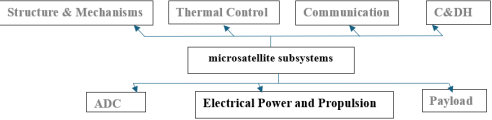
Figure 1. Microsatellite Subsystems.
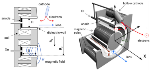
Figure 2. Hall Effect Thruster.
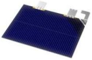
Figure 3. Triple-junction GaAs Solar Panel.
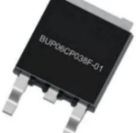
Figure 4. Rad-tolerant P-channel Mosfet for Space.
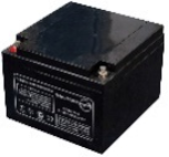
Figure 5. Hermetic Sealed Battery AGM VRLA 12V 26Ah.
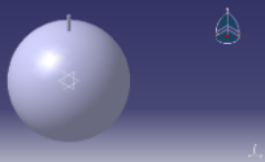
Figure 6. Propellant Tank with Extinction Pipe with the Same Thickness (1.5 mm) and 2.5 mm Hole.

Figure 7. ARM Cortex-M7 CPU.
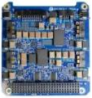
Figure 8. GAUSS PCDU PDB Board.
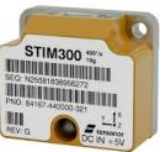
Figure 9. Sensonor STIM300.
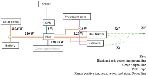
Figure 10. Electrical Power System (EPS) and Propulsion Subsystem.
Information