To use the hole diameter variation method using the partial stress release method by parallel drilling in determining the initial plane stress state of the rock mass, the stress state change surrounding the main measuring hole by parallel drilling is derived and the results are verified by numerical simulations. In the partial stress relief method based on parallel drilling method, firstly, the main measurement hole is drilled to appropriate depth, and then the sensor which is designed and developed to measure the diametrical deformations in three different directions (in general they are apart 120° from each other) is installed in the main hole to sense the hole diametrical change, and then multiple parallel stress relief holes (approximately four at 90°) are drilled at regular intervals next to the core without drilling a larger hole which has coincident center with the main hole as in the complete stress relief method. The diametrical change due to the release of stress surrounding the main measuring hole is then measured using the diametrical deformation gage and through them the initial plane stress state of the rock mass is determined. The numerical simulation results of this method show that the reliability of the partial stress release method compared to the full stress release method can reach more than 99%.
| Published in | Science Discovery Physics (Volume 1, Issue 2) |
| DOI | 10.11648/j.sdp.20260102.13 |
| Page(s) | 108-117 |
| Creative Commons |
This is an Open Access article, distributed under the terms of the Creative Commons Attribution 4.0 International License (http://creativecommons.org/licenses/by/4.0/), which permits unrestricted use, distribution and reproduction in any medium or format, provided the original work is properly cited. |
| Copyright |
Copyright © The Author(s), 2026. Published by Science Publishing Group |
In-situ Stress, Deformation of Diameter, Strain
 ,
,  and
and  , when applying the full stress release method.
 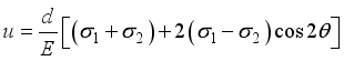 (1)
(1) 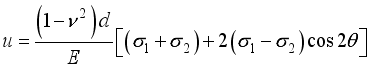 (2)
(2)  -diametric deformation,
  -diameter of hole,
  -elastic modules of rock,
  -poisson coefficient,
  ,
,  -maximum and minimum principle stress,
  -the angle of the direction of maximum principle stress to the direction of the diameter.
 Index | Characteristics |
|---|---|
Dimensions | 700×500×100 mm |
Elastic modules |
|
Poisson coefficient | 0.28 |
density | 7700 kg/m3 |
 (3)
(3)  (4)
(4) Stress (MPa) | DD, μm | ||
|---|---|---|---|
1 | 2 | 3 | |
10 | -6 | -2.2 | -2.2 |
20 | -12 | -5.7 | -5.7 |
30 | -18 | -8.8 | -8.8 |
40 | -24 | -11.7 | -11.7 |
50 | -31 | -14.6 | -14.6 |
Stress (MPa) | Simulated value, μm | Calculated value, μm | ||||
|---|---|---|---|---|---|---|
1 | 1 | 3 | 1 (0°) | 2 (60°) | 3 (120°) | |
10 | -6 | -6 | -2.2 | -5.97 | -2.2 | -2.2 |
20 | -12 | -12 | -5.7 | -11.9 | -5.7 | -5.7 |
30 | -18 | -18 | -8.8 | -17.9 | -8.8 | -8.8 |
40 | -24 | -24 | -11.7 | -23.8 | -11.7 | -11.7 |
50 | -31 | -31 | -14.6 | -29.8 | -14.6 | -14.6 |
Stress (MPa) | DD, μm | ||
|---|---|---|---|
1 | 2 | 3 | |
10 | -4.50 | -1.44 | -1.44 |
20 | -8.99 | -2.87 | -2.88 |
30 | -13.48 | -4.30 | -4.31 |
40 | -17.98 | -5.71 | -5.73 |
50 | -22.46 | -7.12 | -7.12 |
Stress (MPa) | Befor releasing, μm | After releasing, μm | ||||
|---|---|---|---|---|---|---|
1 | 1 | 3 | 1 (0°) | 2 (60°) | 3 (120°) | |
10 | -6 | -2.2 | -2.2 | -4.50 | -1.44 | -1.44 |
20 | -12 | -5.7 | -5.7 | -8.99 | -2.87 | -2.88 |
30 | -18 | -8.8 | -8.8 | -13.48 | -4.30 | -4.31 |
40 | -24 | -11.7 | -11.7 | -17.98 | -5.71 | -5.73 |
50 | -31 | -14.6 | -14.6 | -22.46 | -7.12 | -7.12 |
Stress (MPa) | DD, μm | ||
|---|---|---|---|
1 | 2 | 3 | |
10 | 1.50 | 0.78 | 0.78 |
20 | 3.01 | 2.82 | 2.82 |
30 | 4.52 | 4.49 | 4.49 |
40 | 6.02 | 5.97 | 5.97 |
50 | 7.54 | 7.48 | 7.48 |
DD | Deformation of Diameter |
| [1] | Fairhurst C. Measurement of in situ rock stresses with particular reference to hydraulic fracturing. Felsmech Ingenieurgeol 1964; 3–4: 129–47. |
| [2] | Haimson BC. The hydraulic fracturing method of stress measurements: theory and practice. In: Hudson JA, editor. Comprehensive rock engineering—principles, practice & projects, vol. 3. Oxford: Pergamon Press, 1993. p. 395–412. |
| [3] | Janson T, Stigsson M. Test with three different stress measurement methods in two orthognal boreholes. SKB Technical report R-02-26. Sweden: Stockholm; 2002. |
| [4] | Rocha M. A newtechnique for applying the method of the flat jack in the determination of stress inside rock masses. Proceedings of the First International Congress ISRM. Lisbon, 1966. p. 57–65. |
| [5] | Teufel LW. Insights into the relationship beteween wellbore breakouts, natural fractures and in situ stress. Proceedings of the 26th US Symposium on Rock Mech. Rapid City, 1985. p. 1199–206. |
| [6] | Obert L. In situ determination of stress in rock. Min Eng 1962; 14(8): 51–8. |
| [7] | Leeman ER. The measurement of stress in rock—Part I, II, III. J. South Afr Inst Min Metall 1964; 65: 45–14, 254–84. |
| [8] | Leeman ER. The doorstopper and triaxial rock stress measuring instruments developed by the CSIR. J South Afr Inst Min Metall 1969; 69: 305–39. |
| [9] | Sugawara K, Obara Y, Kaneko K, Aoki T. Hemispherical-ended borehole technique for measurement of absolute rock stress. Proceedings of the International Symposium Rock Stresses and Rock Stress Measurements. Stockholm, 1986. p. 207–16. |
| [10] | Bickel DL. Overcoring equipment and techniques used in rock stress determination (An update of IC 8618). US Bureau of Mines, IC 9013, 1985, 27p. |
| [11] | Martin CD, Christiansson R. Overcoring in highly stressesd granite–The influence of microcracking. Int J Rock Mech Min Sci Geomech Abstr 1991; 28(1): 53–70. |
| [12] | Hiramatsu Y, Oka Y. Determination of the stress in rock unaffected byboreholes or drifts from measured strains or deformations. Int J Rock Mech Min Sci 1968; 5: 337–53. |
| [13] | Leeman ER. The determination of the complete state of stress in rock in a single borehole—laboratory and underground measurements. Int J Rock Mech Min Sci 1968; 5: 31–56. |
| [14] | Leeman ER. The CSIR doorstopper and triaxial rock stress measuring instruments. Rock Mech 1971; 3: 25–50. |
| [15] | Worotnicki G, W alton RJ. Triaxial hollowinclusion gauges for determination of the state of stress in rock masses. Proceedings of the International Symposium on the Determination of Stress in Rock Masses. Lisbon, 1976. p. 405–30. |
| [16] | Worotnicki G. CSIRO triaxial stress measurement cell. In: Hudson JA, editor. Comprehensive rock engineering—principles, practice & projects, vol. 3. 1993. p. 329–94. |
| [17] | Rocha M, Silverio A. A new method for the complete determination of the state of stress in rock masses. Geotechnique 1969; 19(1): 116–32. |
| [18] | Bock H, Foruria V. A recoverable borehole slotting instrument for in situ stress measurements in rock not requiring overcoring. Proceedings of the International Symposium on Field Measurements in Geomechanics, vol. 1. Zurich, 1984. p. 15–29. |
| [19] | Bock H. Measuring in situ rock stress by borehole slotting. In: Hudson JA, editor. Comprehensive rock engineering—principles, practice & projects, vol. 3. Oxford: Pergamon Press, 1993. p. 433–43. |
| [20] | Teufel LW. Prediction of hydraulic fracture azimuth from anelastic strain recovery of measurements of oriented core. Proceedings of the 23rd US Nat. Rock Mech. Symposium. Berkeley, 1982. p. 238–46. |
| [21] | Ren N-K, Roegiers J-C. Differential strain curve analysis—a new method for determining the pre-existing in situ stress state from rock core measurements. Proceedings of the Fifth International Congress ISRM. Melbourne, 1983. p. F79–F83. |
| [22] | Obert L, Stephenson DE. Stress conditions under which core discing occurs. Trans Soc Min Eng AIME 1965; 232: 227–35. |
| [23] | Ribacchi R. Rock stress measurements in anisotropic masses. Proceedings of the International Symposium on Field Measurements in Rock Mech, vol. 1. Zurich, 1977.183–96 p. |
APA Style
Ri, H., Sin, M., Kim, D. (2026). Application of Partial Stress Release Method by Parallel Drilling to Determine the Initial Plane Stress State of Rock Mass Using Hole Diameter Variation Method. Science Discovery Physics, 1(2), 108-117. https://doi.org/10.11648/j.sdp.20260102.13
ACS Style
Ri, H.; Sin, M.; Kim, D. Application of Partial Stress Release Method by Parallel Drilling to Determine the Initial Plane Stress State of Rock Mass Using Hole Diameter Variation Method. Sci. Discov. Phys. 2026, 1(2), 108-117. doi: 10.11648/j.sdp.20260102.13
@article{10.11648/j.sdp.20260102.13,
  author = {HyonHyok Ri and Myong-Nam Sin and Dae-Song Kim},
  title = {Application of Partial Stress Release Method by Parallel Drilling to Determine the Initial Plane Stress State of Rock Mass Using Hole Diameter Variation Method},
  journal = {Science Discovery Physics},
  volume = {1},
  number = {2},
  pages = {108-117},
  doi = {10.11648/j.sdp.20260102.13},
  url = {https://doi.org/10.11648/j.sdp.20260102.13},
  eprint = {https://article.sciencepublishinggroup.com/pdf/10.11648.j.sdp.20260102.13},
  abstract = {To use the hole diameter variation method using the partial stress release method by parallel drilling in determining the initial plane stress state of the rock mass, the stress state change surrounding the main measuring hole by parallel drilling is derived and the results are verified by numerical simulations. In the partial stress relief method based on parallel drilling method, firstly, the main measurement hole is drilled to appropriate depth, and then the sensor which is designed and developed to measure the diametrical deformations in three different directions (in general they are apart 120° from each other) is installed in the main hole to sense the hole diametrical change, and then multiple parallel stress relief holes (approximately four at 90°) are drilled at regular intervals next to the core without drilling a larger hole which has coincident center with the main hole as in the complete stress relief method. The diametrical change due to the release of stress surrounding the main measuring hole is then measured using the diametrical deformation gage and through them the initial plane stress state of the rock mass is determined. The numerical simulation results of this method show that the reliability of the partial stress release method compared to the full stress release method can reach more than 99%.},
 year = {2026}
}
TY  - JOUR
T1  - Application of Partial Stress Release Method by Parallel Drilling to Determine the Initial Plane Stress State of Rock Mass Using Hole Diameter Variation Method
AU  - HyonHyok Ri
AU  - Myong-Nam Sin
AU  - Dae-Song Kim
Y1  - 2026/04/23
PY  - 2026
N1  - https://doi.org/10.11648/j.sdp.20260102.13
DO  - 10.11648/j.sdp.20260102.13
T2  - Science Discovery Physics
JF  - Science Discovery Physics
JO  - Science Discovery Physics
SP  - 108
EP  - 117
PB  - Science Publishing Group
SN  - 3071-5458
UR  - https://doi.org/10.11648/j.sdp.20260102.13
AB  - To use the hole diameter variation method using the partial stress release method by parallel drilling in determining the initial plane stress state of the rock mass, the stress state change surrounding the main measuring hole by parallel drilling is derived and the results are verified by numerical simulations. In the partial stress relief method based on parallel drilling method, firstly, the main measurement hole is drilled to appropriate depth, and then the sensor which is designed and developed to measure the diametrical deformations in three different directions (in general they are apart 120° from each other) is installed in the main hole to sense the hole diametrical change, and then multiple parallel stress relief holes (approximately four at 90°) are drilled at regular intervals next to the core without drilling a larger hole which has coincident center with the main hole as in the complete stress relief method. The diametrical change due to the release of stress surrounding the main measuring hole is then measured using the diametrical deformation gage and through them the initial plane stress state of the rock mass is determined. The numerical simulation results of this method show that the reliability of the partial stress release method compared to the full stress release method can reach more than 99%.
VL  - 1
IS  - 2
ER  -
Faculty of Mining Engineering, Kim Chaek University of Technology, Pyongyang, DPR of Korea
Faculty of Mining Engineering, Kim Chaek University of Technology, Pyongyang, DPR of Korea
Faculty of Earth Science and Technology, Kim Chaek University of Technology, Pyongyang, DPR of Korea
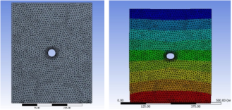
Figure 1. Numerical model.
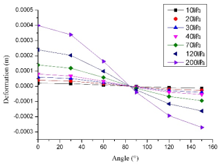
Figure 2. DD under the diverse loading and directions.
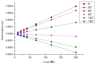
Figure 3. DD for diverse direction with the increase of load.
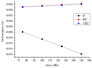
Figure 4. Relationship of DD with the magnitude of loading.
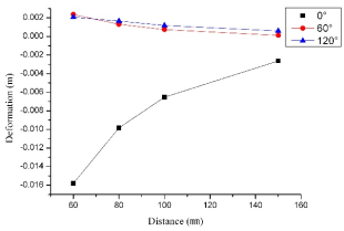
Figure 5. Relationship of DD with the distance of holes.
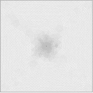
Figure 6. Meshing diagram of model.
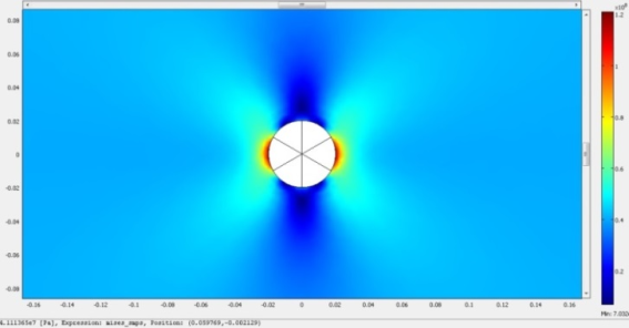
Figure 7. Von-misses stress around the main hole.
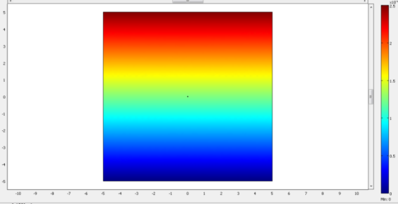
Figure 8. The simulation result of vertical deformation.
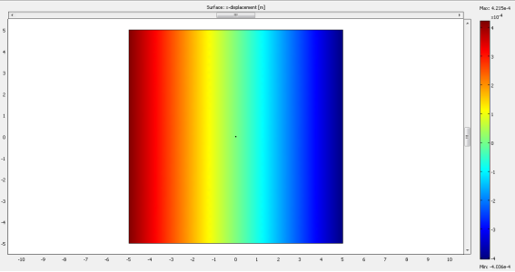
Figure 9. Simulation result of horizontal deformation.
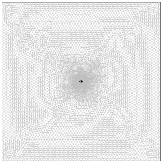
Figure 10. Meshing diagram of model.
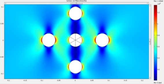
Figure 11. Equivalent stress distribution diagram.
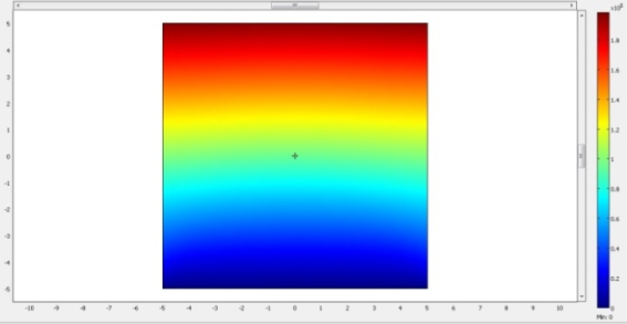
Figure 12. Vertical deformation distribution.
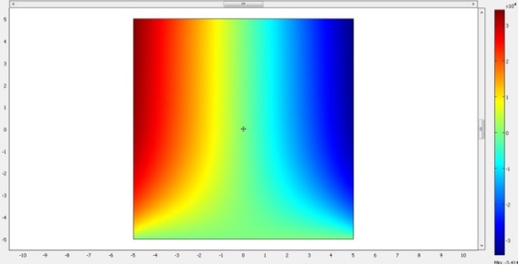
Figure 13. Horizontal deformation distribution.
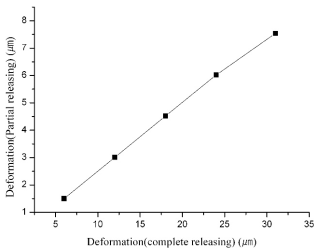
Figure 14. Comparing of the DD in the case of partial and complete stress relief method.
Information


 MPa
MPa